External Fixation (Ex-Fix) Configurations for Common Fractures

Warning

Objectives

The purpose of this guideline is to describe the application of external fixation (Ex-Fix) devices in the management of common fractures encountered during deployed surgical care. These devices are used to achieve skeletal stabilisation, particularly in resource-constrained settings.

Scope

This guideline is targeted for use across all echelons of deployed surgical care.

Audience

The audience for this document is deployed surgical team and medical support staff.

Initial Assessment & Management

Initial Assessment and Management

Injury Identification

Perform a systematic assessment to identify fractures, ensuring imaging (portable X-ray) when available. Document wound contamination, neurovascular status, and compartment syndrome signs (As per CGO Acute Compartment Syndrome and Fasciotomy). Open fracture management performed as per Wound Excision CGO concurrent to the following principles.

Principles of Fracture Management

Splint and immobilise fractures. This aids analgesia requirements and protects the soft tissue envelope associated with a traumatic injury. Assess whether the fracture needs to be reduced; and whether this can be achieved with non-invasive indirect methods such as casting, splintage or bracing. If fracture reduction is required and is not able to be held by non-invasive means, or the nature of associated injuries mandates skeletal stabilisation then consider the application of an External Fixator device.

General Principles of External Fixation

External fixation aims to achieve skeletal stabilisation through an external scaffold composed of pins and bars. This technique can serve as either temporary or definitive management. The advantages of external fixation in severe injury are due to the minimal soft tissue insult associated with the application. This enables vascular assessment and management, as well as wound debridement. The application can be expeditious, causing minimal interference with the wider resuscitation process and does not rely on radiography. Once stabilisation is achieved it optimises ongoing neurovascular assessment, patient handling, pain, and wound care. Vigilance is required to prevent complications, particularly pin site infection. Other complications include neurovascular injury, implant loosening, osteomyelitis and mechanical failure. Regular review and diligent application techniques are required to reduce this risk.

Pin Selection: The diameter of the pin size confers increased mechanical stability. A pin size should be between 1/4 and 1/3 of the diameter of the bone. Greater than 1/3 width risks fracture. Pin sizes will vary with anatomical location; see typical pin sizes below:

  • Metatarsal – 3 mm (use of the 3/5 mm Hybrid Half Pin)
  • Calcaneus – (5 mm Transfixing pin; also known as Denham pin)
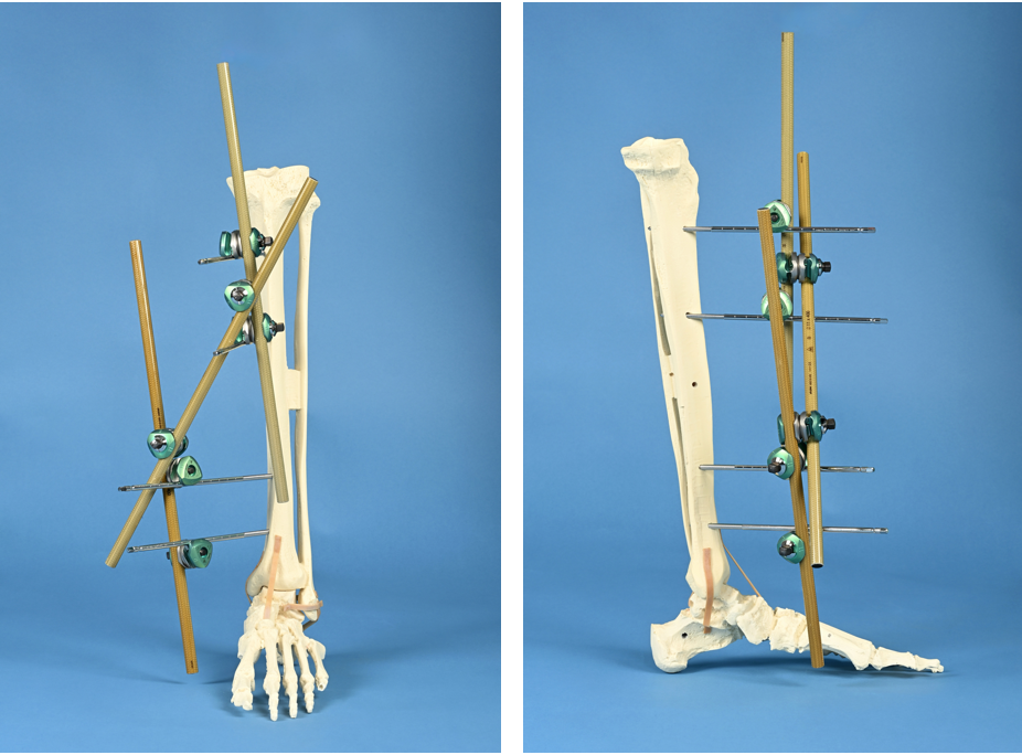
  • Tibia – 5 mm Half Pin
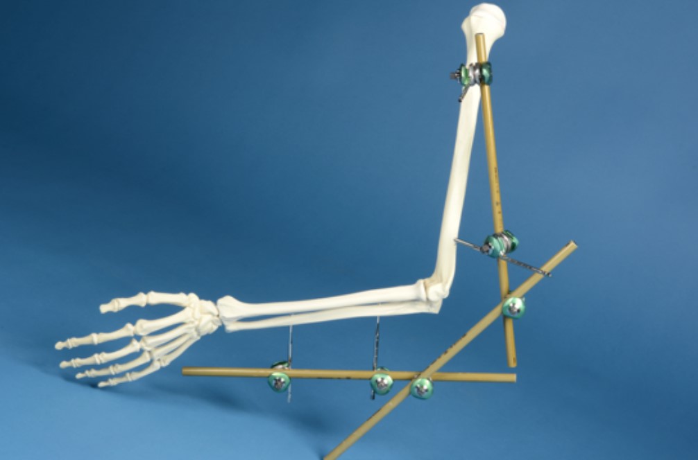
  • Femur – 5 mm Half Pin
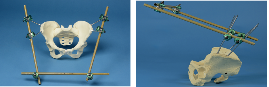
  • Pelvis – 5 mm Half Pin
  • Humerus – 5 mm Half Pin proximally, 3 mm (3/5 mm Hybrid Half Pin) distally
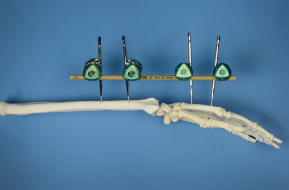
  • Radius/Ulna – 3 mm (use of the 3/5 mm Hybrid Half Pin)
  • Metacarpal – 3 mm (use of the 3/5 mm Hybrid Half Pin)

The use of Hybrid 3/5 pins in the Hoffman 3 system allows a smaller cortical diameter to be used with a connection element of a larger diameter. These are represented with numerical/numerical description with the former representing the diameter of the threaded portion of the half pin and the latter the diameter of the non-threaded shank portion for application to a connector.

Pin placement: Safe corridors of anatomic locations for pins are demonstrated within injury-specific configurations below. Principles of pin placement are: avoidance of neurovascular bundles, avoidance of tethering muscle, interference of contralateral limb or areas subjected to pressure, ability to nurse the patient in supine/seated position, avoidance of heavily contaminated wounds; maintenance of vascular access (of particular importance in polytrauma casualties).

Frame Assembly: Principles of near-far pin placement (2 pins per fragment placed 1 close to fracture and 1 far from fracture) to obtain fragment stability. Consideration of avoidance of zone of injury and preservation of future operative tissue being invaded is beneficial. Ensure a minimal gap of approximately 2 cm exists between the connecting bars and the soft tissue to allow room for ongoing swelling.

Stability Considerations: Construct stability is aided by increased diameter of pins, increased number of pins, increased diameter of bars, increased number of bars, multiplanar constructs, and reduction of distance between bone and bar. Ultimately, construct stability within the context of a fracture is most stable with a successful reduction.

Componentry

The Hoffmann 3 External Fixation hardware is coordinated into three different packs/trays with individual supplementary packed items as required. From the perspective of the deployed role, these are available in two main forms: Field Kit B and the Hoffmann External Fixation System.

Field Kit B was specifically designed with the intention to deliver a forward deployed surgical pack. The formal title is “Field Kit B Hoffmann 3 Augmentation Kit”. For most of the injury patterns described in this guideline, management is presented with the aim of using minimal equipment, ideally relying on a single field pack (Field Kit B) whenever possible. The Field Kit B componentry importantly does not include Hybrid 3/5mm Apex Half Pins (for use in the upper limbs or metatarsals). At present, these must be packed and sterilised separately so may not be available in every deployed environment. The transfixation (Denham) pin is available as an individual pre-packaged and sterilised component. See below under “Supplementary Componentry”.

The Hoffmann External Fixation System is a full tray of interchangeable components and instrumentation to give the operator a wider choice and volume of hardware to augment the management of the injury. The availability of these components allows greater flexibility and tailoring of fixation to enhance stability and soft tissue protection.

 Field Kit B (NSN 6516-01-627-9042)

Reference

NSN

Description

Quantity

4922-1-010

6515-01-600-4116

Delta Rod-to-Rod Coupling 5/8/11 mm Rods and 5 mm Pins

6

4922-8-400

6515-01-600-3377

Vectran coated Connecting Rod Ø11 x 400mm

3

4922-8-400

6515-01-513-1261

Apex Pin Ø5mm, 180 x 50mm, self-drilling

4

VIM-0

6515-01-208-5966

Drill Brace for Apex Pins and Couplings / Clamps

1

SW A-S10

NA

No.10 Scalpel

1

32-01241

NA

Mosquito Hemostat Clamp

1

Hoffmann 3 External Fixation System Tray

Reference

NSN

Description

Quantity

4922-9-950

6530-01-621-1211

Level 3/4/5 Military Plastic Tray

1

4922-1-015

6515-01-604-7102

Multiplanar Rod to rod-to-rod coupling

4

4920-9-020

6515-01-522-4925

Thumbwheel

2

5026-1-150

6515-01-600-4144

4 mm x 150 mm, 40 mm THD SD/ST Apex Half Pins

12

5026-8-120

6515-01-600-4135

Hybrid 3/5 mm Hoffmann Apex Pin

25

5018-6-180

6515-01-513-1261

5 mm x 180 mm, 50 mm Apex Half Pins

26

5018-5-150

6515-01-503-9984

5 mm x 150 mm, 40 mm Apex Half Pins

10

5050-4-300

6515-01-604-0767

5 mm x 300 mm, 40 mm Central thread

2

4922-1-010

6515-01-600-4116

Delta Rod-to-Rod Coupling 5/8/11 mm Rods and 5 mm Pins

16

4922-9-140

6515-01-600-3334

Soft tissue protector

2

4922-9-240

6515-01-600-3365

Trocar

2

4922-7-220

6515-01-600-3370

Semi-circular rod 11 mm x 400 mm

2

4920-9-036

6515-01-208-5963

7 mm Spanner Wrench

1

5057-0-300

6515-01-208-5966

Apex Drill Brace 3/4/5/6MM

1

4922-9-050

6515-01-600-3340

AO/Jacobs Quick Release Apex 4/5/6 mm Chuck

1

5028-8-400

6515-01-567-4036

MRI Safe Connecting Rod 8x400mm

4

5028-8-300

6515-01-567-4047

MRI Safe Connecting Rod 8x300mm

2

4920-9-030

6515-01-583-5135

7 mm T-wrench 4/5/6 mm Pin Driver

1

4922-8-300

6515-01-600-3362

Carbon Connecting Rod 11 mm x 300 mm

2

4922-8-400

6515-01-600-3377

Carbon Connecting Rod 11 mm x 400 mm

4

Supplementary Componentry

Reference

NSN

Description

Quantity

5018-6-180

6515-01-600-4135

Hybrid Apex Pin Ø3/5mm, 120 x 20mm, self-drilling

-

5050-4-300

6515-01-604-0767

5 mm x 300 mm, 40 mm Central thread

-

Infection

Antibiotic prophylaxis should be administered within 1 hour prior to knife-to-skin. Ongoing antibiotic prescription is not a pre-requisite of external fixator application but is related to the overall injury profile. The importance of soft tissue protection is vital for infection prevention. Skin tenting at pin sites should be prevented.

Post-Operative Principles

Reassess neurovascular status post-application. Simple elevation of the limb aids post-operative swelling and pain. Reassessment of construct stability is required at regular intervals. Patient positioning and pressure areas related to the frame must be checked. Joint mobilisation proximal and distal to the frame may be achieved to prevent contracture and discomfort. Always consider the pressure effect that the frame itself could have on other body sites such as the contralateral limb.

Wound Care

Simple wound dressings are applied to the external fixator pin sites after application. This is composed of an antiseptic-soaked swab at the base of the pin site. Ongoing pin site care is described in the prolonged field care section.

Advanced Assessment & Management

External Fixator Surgical Guidelines

These surgical guidelines are designed to act as a handrail for a standardised approach to the configuration of an External Fixator. Individual injury profiles will dictate the exact configuration of the construct. Apply the general principles of external fixation to complex injuries to allow skeletal stabilisation, protection of soft tissues and multi-speciality management.

The individual configurations have been described to use minimal equipment, primarily relying on a single Hoffman 3 Field Kit B pack when possible.

General Surgical Considerations for Usage of Hoffman 3 External Fixator

Apex Half Pins: Apex half pins are self-drilling and self-tapping; no predrilling is required. Insert perpendicular to the bone and centrally through its cross-section. Bicortical purchase should be attained for optimal stability (excluding the placement of pelvic pins). Pins are inserted manually using a drill brace with soft tissue protection. Constant steady pressure with clockwise rotation of the brace facilitates advancement. A reduction in resistance will be palpable after the first cortex. The next increase of resistance will represent the far cortex; advancement of up to 6 complete revolutions of the drill brace enable full bicortical purchase. Ensure that the skin and muscle are not tented on the half pin as this raises the chance of associated infection. Hybrid half pins are inserted in the same manner, the brace is interchangeable.

In extremis, the brace itself can be used as an ex-fix bar because it has the same diameter at the ex-fix bars and it does fit into the connectors. This statement is not a recommendation for this, but the deployed surgeon may find this information useful in resource-constrained settings.

Transfixing Pin: The 300 mm transfixing pin (Denham pin) features a 6mm threaded portion in the centre of the shank. Unlike the apex pins, it is advanced fully through the far cortex and until the threaded portion achieves bicortical engagement. The tip of the pin to requires a skin incision at the far side to accommodate it passage. To reduce the risk of iatrogenic injury a bung or protective cap may be applied to the exposed end of the pin.

Connectors: The Hoffmann kit uses Delta Couplings to link rods and pins via a ‘snap-to-fit’ mechanism. Rod-to-rod couplings (green/green) accommodate 8 and 11mm rods to 5mm pins. Rod-to-pin couplings (grey/green) support 4, 5, and 6-mm apex pins. All couplings feature a preassembled thumbwheel for provisional tightening, which may be snapped off and replaced, or once removed definitively tightened with the drill brace (which doubles as a wrench). For best fit, a coupling may serve as a drill guide when provisionally placed on a rod during insertion of the second pin.

Rods: The system uses Vectran-coated carbon fibre rods (also known as bars). Field Kit B includes three 11×400 mm rods. The External Fixation System includes additional length and diameters of rods as detailed in the componentry section.


See Below for Configurations for Specific Anatomical Areas

Prolonged Casualty Care

Stabilisation: Ensure frame integrity and reassess alignment regularly. Daily check of connector tightness. If concerns, additional stability can be achieved as per the general principles section.

Infection Prevention: A high degree of vigilance is required for pin site care; the pin sites should be checked daily. The spectrum of pin site issues can range from irritation to deep infection. If infection is suspected, then prompt administration of antibiotics is indicated with clinical reassessment.

Pin site Cleaning: This should occur weekly in the form of an antiseptic solution such as alcoholic chlorhexidine. Simple dressings can be reapplied as required. These dressings should be non-shedding. A compression clip to press the dressing against the skin can aid patient discomfort; a clip, bung or bandage can be used. Care must be taken not to push the clip and dressings down onto the skin too hard or else tissue necrosis can result. Once pin sites have become dry there is no requirement to apply any superficial dressings. However, in the deployed setting, dressings are recommended due to the austere environment and challenges with environmental cleanliness. The frequency of pin site cleaning may require to be increased in the presence of infection. Bathing is contraindicated. Showers are tolerated on the day of pin site care prior to dressing change; after showering the pin sites are carefully dried and new dressings applied. Pin sites that become painful, swollen, and discharging may be treated with oral antibiotics according to the Deployed Antimicrobial Guidelines. In severe cases of pinsite infection, the affected pin may have to be removed and re-sited.

Movement: Encouragement of proximal and distal movement of limbs once stabilised with external fixators prevent contractures. Regular positional change of patients to prevent pressure areas is critical.

Swelling: The severity of swelling can increase with time duration from injury; check that skin clearance to bars and connectors remains adequate. Simple elevation aids the improvement of soft tissue swelling. Always consider the risk of compartment syndrome.

Construct adjuncts: Consider construct of construct adjuncts such as a kickstand to allow the affected limb to be suspended; encouraging complete assessment of the affected limb. Take care to ensure constructs do not cause iatrogenic injury to the other limb or body regions via pressure.

Paediatric Considerations

Anatomical Considerations

  • Use smaller pins for paediatric anatomy; apply general principles in consideration of pin diameter selection. Aim for pin diameter >1/4 but <1/3 of cortical-cortical width
  • Avoid the physis when placing pins to prevent the risk of growth disturbance. In consideration of this, a minimum distance of 2 cm is recommended to prevent the risk of damage.

Monitoring and Adjustments

  • Reassess frequently to address potential complications such as pin-site infection or construct loosening, which may occur more rapidly in children.

Definitive Fixation

  • Due to the decreased duration of bone healing in a paediatric patient consider whether the external fixator may be used as a definitive device.

Ankle Spanning External Fixator

Indications: Distal tibia fracture, ankle fracture/dislocation, pilon fracture, talar fracture/dislocation.

Equipment Required: 1x Scalpel No.10, 1x Mosquito Haemostat Clamp, 1x Drill Brace, 2x 5 mm Apex Half Pins, 1x 5/6mm transfixing pin [Supplementary], 6x Delta Couplings, 3x 11x400 mm Connecting Rods. [Additional equipment such as the 3/5 hybrid pin may be used when resource constraints allow].  Antiseptic-soaked gauze swab for pin sites.

Patient Position: Supine/crucifix. All dressings are removed and a social wash is performed using betadine and water.

Prep and Drape: Prep the entirety of the foot and extend proximally to above the knee. U-shape drapes fashioned from universal drapes and applied above the knee. Bump (rolled drape) under the ipsilateral ankle.

Fig 1 Ankle Spanning Simple AP View


Fig 2 Ankle Spanning Simple Lat View


Procedural Technique: Address proximal pin placement first. Identify the anteromedial aspect of the tibia, this presents a flat and wide target area for pin placement. Pin placement should not involve the zone of injury. A minimum of 2 finger breadths from the fractured region is appropriate. A scalpel is used to incise the skin enough to allow passage of the pins. The mosquito is used to spread the subcutaneous tissues exposing the bone. An Apex 5 mm half pin is inserted by hand as per the description in the general surgical considerations using the drill brace. A further Apex 5 mm half pin is placed in the same manner.

Attention then is turned to the placement of the transfixing pin. This is placed into the calcaneus from medial to lateral. The posterior tibial artery is palpated if possible; if not then palpation of the contralateral side may guide approximate position. Using bony landmarks when palpable, the safe zone of entry is posterior to the halfway point between the inferior aspect of the medial malleolus and the postero-inferior aspect of the calcaneus. Particular caution should be taken to carefully expose the subcutaneous tissues to protect any neurovascular/ tendinous structures. The pin is advanced perpendicular to the calcaneus axis. The transfixing pin is advanced completely through the far cortex and a small skin incision on the lateral side is made to allow complete advancement. The threaded area of the pin located centrally should sit intraosseous and increased resistance to advancement be felt when the thread first begins to engage. A bung or rubber tip may be placed on the pin tip after transfixing to prevent iatrogenic injury to the operating team.

With the vital pins now insitu the initial construct configuration can be established [see clinical photograph above]. Delta couplings are applied to each tibial pin, as well as to the medial and lateral aspect of the transfixing pin. These couplings are then attached to connecting rods are placed medially and laterally to form a triangle shape; joining the medial and lateral aspects of the transfixing pin and the tibial pins. These are provisionally secured ensuring adequate position so as not to interfere with knee and ankle access. These couplings are only tightened loosely using the thumbwheel so as to still allow some degree of movement. A rod connecting the two proximal pins can also be placed to increase construct stability; these couplings specifically can be maximally tightened.

Ankle reduction is then performed with in-line traction and manual correction of any persisting deformity. With limb alignment, length and rotation restored; the remaining delta couplings are tightened initially with the thumbwheel maximally. The construct is then further evaluated and final tightening is performed using the Drill Brace. Ankle dorsiflexion can be achieved simply with the application of a bandage with the tibial pin site as a fulcrum or a metatarsal pin placed when resources permit as described below [see clinical photograph below].

Special Considerations: Ankle dorsiflexion can help maintain reduction and prevent equinus contracture. To enable this a 3/5mm Hybrid half pin can be placed into the 1st metatarsal. The pin site location for this region is the medial aspect of the metatarsal which is palpable under the skin. A small incision is made into the medial aspect of the forefoot at the midpoint of the 1st metatarsal. Soft tissues are protected and a 3/5mm hybrid pin inserted in the standard technique. This is connected via a delta rod-rod coupling to a connecting rod; this rod is connected proximally to the medial triangular rod using a rod-rod coupling. The foot is brought into a plantigrade position and the couplings are tightened as per standard fashion. The images below demonstrate this technique with the proximal tibial rod removed to aid visualisation.

Fig 3 Ankle Spanning (Supplemented) AP View
Fig 4 Ankle Spanning (Supplemented) Lat View

A kickstand can be added to enable the heel to be elevated and prevent pressure areas. To configure this, the External Fixation System tray has a semi-circular 11x220 mm rod which attaches to the medial and lateral triangular struts using rod-rod couplings. In the absence of a semi-circular rod, this can be recreated with 3 rods and 4 coupling attachments.

Additional stability can be facilitated as per the ‘General Principles of External Fixator’ section; classically for this construct, it is achieved via a further rod connecting the medial and lateral triangular rods to form an A-shape.

An alternate configuration to the delta frame is the medial unilateral ankle fixator. This uses the same tibial half pins; however, a half pin is placed into the calcaneus rather than a transfixing pin. A hybrid half pin is placed into the 1st metatarsal medial aspect. As per the principles above, these two segments (tibia-tibia and calcaneus-metatarsal) are provisionally connected in an L shape construct; reduction is performed and sequential tightening. A further rod is placed to form a triangle connecting the tibia-tibia rod and the calcaneus-metatarsal rod. This configuration can be constructed for the lateral side also with the use of the 5th metatarsal instead of the 1st. [see clinical photography below]

Fig 5 All-Medial Ankle Ex Fix, AP View
Fig 6 All-Medial Ankle Ex Fix, Medial View

Tibia External Fixator

Indications: Mid-shaft tibia fractures that are unable to be controlled with a splint or in the context of extensive soft tissue injury/compartment syndrome/open.

Equipment Required: 1x Scalpel No.10, 1x Mosquito Haemostat Clamp, 1x Drill Brace, 4 x 5 mm Apex Half Pins, 6x Delta Couplings, 2 x 11x400 mm Connecting Rods.  Antiseptic-soaked gauze swab for pin sites.

Patient Position: Supine

Prep and Drape: Prep the entirety of the foot and extend proximally to above the knee. U-shape drapes fashioned from universal drapes and applied above the knee. Bump (rolled drape) under the ipsilateral ankle.


Fig 7 & 8 AP and Medial views of tibia ex-fix

Procedural Technique: Follow the general external fixator protocol as stated above. Address proximal fragment pin placement first. Identify the anteromedial aspect of the tibia, this presents a flat and wide target area for pin placement.

A minimum of 2 finger breadths from the fractured region or soft tissue injury is appropriate. A scalpel is used to incise the skin. The mosquito is used to spread bluntly the subcutaneous tissues exposing the bone. An Apex 5 mm half pin is inserted by hand as per general surgical considerations. A further 5 mm apex half pin is inserted by hand using the drill brace in the proximal fragment.

Place the distal pins in the same manner. Avoid anterior tibial vessels and deep peroneal nerve by continuing to use the anteromedial safe zone. Take care to direct the pin perpendicular through the centre of the distal tibia, this will aid prevention of any over-penetration risking injury to the posterior tibial neurovascular bundle.

The tibial pin sites are connected using a rod-rod coupling at each half pin and a connecting rods. Fracture reduction is then performed with in-line traction and manual correction of any persisting deformity. With limb alignment, length and rotation restored; the couplings are tightened initially with the thumbwheel, then maximally with the drill brace. Ensure the distance between the connecting rod and the skin can accommodate any swelling.

While technically possible, it is not recommended to attempt to connect all four tibial pins with a single rod. In almost all cases, the direction of the pins does not allow a single linear connecting rod to complete the construct. Even small deviations from a perfectly straight line will lead to either unacceptable malreduction of the fracture or significant bending forces on the hardware.

Special Considerations: Consider placing pins at slightly differing longitudinal positions to avoid propagation of a vertical split fracture from the index injury.

Knee Spanning External Fixator

Indications: Fracture of tibial plateau or proximal tibia, distal third femoral fracture, knee dislocation; or in the context of extensive soft tissue injury, compartment syndrome and open fractures.

Equipment Required: 1x Scalpel No.10, 1x Mosquito Haemostat Clamp, 1x Drill Brace, 4 x 5 mm Apex Half Pins, 3 x 11x400 mm Connecting Rods, 6x delta coupling.  Antiseptic-soaked gauze swab for pin sites.

Patient Position: Supine

Prep and Drape: Prep the entirety of the affected lower limb from hip to foot. U-shape drapes can be fashioned from universal drapes and applied to seal out the perineal region and allow access to the entire femur for pin access. The toes and foot can be covered and sealed off if supplies allow, it is important to retain orientation and use the leg as a guide on rotation.

Fig 9 Knee Spanning AP view
Fig 10 Knee Spanning Lat View

Procedural Technique: Address proximal tibial pin placement first. Identify the anteromedial aspect of the tibia, this presents a flat and wide target area for pin placement.

A minimum of 2 finger breadths from the fractured region or soft tissue injury is appropriate. A scalpel is used to incise the skin. The mosquito is used to spread bluntly the subcutaneous tissues exposing the bone. An Apex 5mm half pin is inserted using the drill brace. A further 5 mm apex half pin is inserted more distally in the same fragment, noting the larger the distance between these two pins the more stable the construct.

The tibial pin sites are connected using a rod-rod coupling at each half pin, and a connecting rod.

Attention is then turned to the femur. The safe areas of the pins in the femur are typically from a direct lateral direction. Avoid placement too distal that may involve the knee joint particularly distal to the epicondyles.

A minimum of 2-3 finger breadths from the fractured region or soft tissue injury is crucial. Incise the skin with the scalpel, and a mosquito to dissect the subcutaneous tissues to bone. Langenbeck retractors may be required to manage the muscle envelope. Two Apex 5mm half pins are inserted into the mid- and distal femur.

Safe zone in the middle third: Palpate the shaft of the femur transcutaneously, when not possible consider an anterior bowed trajectory from the greater trochanter to the lateral epicondyle. Pin placement is in a direct lateral approach.

Safe zone in the distal third: Pins at the distal third of the femur can be inserted from a direct lateral approach. Avoid placement too distal that may involve the knee joint – remain proximal to the epicondyle.

The femoral pin sites are connected using a rod-rod coupling at each half pin and a connecting rod. The femoral and tibial pin-rod constructs are then connected via a further 11x400 mm connecting rod and 2x delta coupling.

The couplings which join the tibia and femoral rods are loosely applied at first. The fragments can be joy-sticked into alignment and the adjoining couplings maximally tightened in position. [see clinical photograph above]. Ensure the distance of the connecting rod from the skin accommodates likely swelling of the tissues.

Special Considerations: Distal femur fractures are at risk of rotational deformity, use the position of the distal limb and resting alignment of the contralateral side as a guide on orientation.

For the tibial construct, consider placing pins at slightly differing longitudinal positions to avoid propagation of a vertical split fracture from the index injury. Couplings can accommodate a small malalignment.

The configuration which confers highest stability is the so called ‘diamond’ or parallel bar knee spanning external fixator. This requires a minimum of four connecting rods and should be considered as resource constraint allows.

Femur External Fixator

Indications: Mid-shaft femur fractures that are unable to be controlled with a splint/KTD/traction; or in the context of extensive soft tissue injury, compartment syndrome and open fractures.

Equipment Required: 1x Scalpel No.10, 1x Mosquito Haemostat Clamp, 1x Drill Brace, 4x 5 mm Pins, 6x Delta Couplings, 3x 11x400 mm Connecting Rods.  Antiseptic-soaked gauze swab for pin sites.

Patient Position: Supine with manual in-line traction.

Prep and Drape: Prep the entirety of the affected lower limb from hip to foot. U-shape drapes can be fashioned from universal drapes and applied to seal out the perineal region and allow access to the groin, proximal hip and buttock. The foot and ankle can be covered and sealed off if supplies allow, it is important to retain orientation and use the leg as a guide on rotation.

Fig 11 Femur AP View
Fig 12 Femur Lateral View

Procedural Technique: Following the principle of external fixators above, the safe areas of the pins in the femur are typically from a direct lateral direction. The principle of two pins in each fracture fragment applies.

Safe zone in proximal third: with the patient supine, palpate the greater trochanter. Depending on the fracture pattern, a pin can be directed towards the lesser trochanter or femoral neck. This can be challenging without fluoroscopy and therefore direct lateral perpendicular pin placement should suffice. Care should be taken to avoid perforation beyond the femoral cortex medially to prevent injury to the neurovascular structures.

Safe zone in the middle third: Palpate the shaft of the femur transcutaneously; when not possible consider an anterior bowed trajectory from the greater trochanter to lateral epicondyle. Pin placement is in a direct lateral approach.

Safe zone in the distal third: Pins at the distal third of the femur can be inserted from a direct lateral approach. Avoid placement too distal that may involve the knee joint – stay proximal to the epicondyle.

A minimum of 2-3 finger breadths from the fractured region or soft tissue injury is appropriate. Skin incision with scalpel, subcutaneous tissue to bone dissected with mosquito. Langenbeck retractors may be required to manage the muscle envelope. An Apex 5 mm pin is inserted with the drill brace. These steps are repeated to achieve two distal and two proximal pins.

As with the tibia (above), it is recommended that the two proximal pins are connected with one rod, the two distal pins with a second rod, and then reduction is achieved with longitudinal traction and direct manipulation of the fragments via these bars. Once reduction is achieved, these two bars are connected with a third bar and two couplings.

Special Considerations: The muscular envelope of the femur is strong, one may consider temporarily stabilising the femoral fracture in a Thomas splint or an alternate method of traction to aid reduction. Femur fractures are at risk of rotational deformity, use the position of the distal limb and resting alignment of the contralateral side as a guide on orientation. With the aid of fluoroscopy; cortical thickness, fracture configuration, and lesser trochanter positioning are all useful adjuncts.

Hip Spanning External Fixator

Indications: To control proximal femoral instability in the context of extensively comminuted proximal femur fracture, or with associated open / soft tissue injury.

Equipment Required: 1x Scalpel No.10, 1x Mosquito Haemostat Clamp, 1x Drill Brace, 4x 5 mm Apex Half Pins, 6x Delta Couplings, 3x 11x400 mm Connecting Rods.

Patient Position: Supine/crucifix. All dressings are removed in the operative field, and a social wash is performed using betadine and water.

Prep and Drape: Apply prep to the entirety of the exposed anterior pelvic region, abdomen up to xiphisternum and proximal aspect of lower limbs as allows in consideration of other injuries. Universal drapes are applied squarely.

Fig 13 Hip Spanning AP View
Fig 14 Hip Spanning Lateral View

Procedural Technique: Address the location of the pin site located at the anterior superior iliac spine first. This can typically be palpated anteriorly. An oblique incision 3-4cm can be placed enabling skin manoeuvrability and palpation of the ilium deep. Blunt dissection using a Mosquito is undertaken to reveal the crest of the ilium. The inner and outer cortices of the ilium can be palpated. To aid a trajectory half pins may be carefully placed on either side of the ilium to act as a guide for the plane for half pin direction. With the patient in a supine position, aim the direction of the half pins towards the acetabulum so the exposed shaft for connection is tilted towards the patient’s head – this will prevent impingement in the future for seated positions. Advance the half pin using the drill brace; there will be no second cortex palpable typically unless trajectory is directed towards inner/outer table. Advance until resistance or estimating insertion depth relative to the length of exposed thread still visible.

Further half pin placement can be located posterior to the initial pin placement on the iliac crest. This can be placed from 2 cm more posterior along the iliac crest, with the same technique as described.

Femoral pins are placed distal from the zone of injury. They should be placed in near-far fashion but with an understanding of the length constraints of the 400 mm connecting rod required to span the pelvis to femur. A trajectory of lateral to medial with a direct lateral approach should be utilised. Skin incised with the scalpel, subcutaneous tissues dissected with mosquito and Langenbeck retractors used if required for significant muscular envelope. Insertion of the pins with the drill brace as per standard technique.

A delta coupling is placed onto each of the femoral pins and a connecting rod is applied to join these pins together with the rod positioned to allow proximal extension of the rod as per the clinical photograph above. Two further connect rods are placed spanning from the anterior pelvic half pin to the femoral connecting rod and from the posterior pelvic half pin to the connecting rod as shown in the clinical photograph. The couplings are loosely applied at the rod to rod couplings but maximally tightened at the pin to rod interfaces.

In line traction to aid reduction, correcting length, alignment and rotation is applied and the rod to rod couplings are then maximally tightened. Appraisal of the skin peripheral to the half pins is then undertaken to ensure there is no tethering. Antiseptic-soaked gauze is applied peripheral to pin sites.

Special Considerations: An additional rod can be supplemented to connect the two pelvic half pins in order to improve stability.

Pelvic External Fixator

Indications: To control pelvic instability in the context of pelvic ring fracture, to enable EPP in which a pelvic splint is unsuitable, or to mitigate the duration of time before definitive pelvic fixation.

Equipment Required: 1x Scalpel No.10, 1x Mosquito Haemostat Clamp, 1x Drill Brace, 4x 5 mm Apex Half Pins, 6x Delta Couplings, 3x 11x400 mm Connecting Rods.

Patient Position: Supine/crucifix. All dressings are removed in the operative field, and a social wash is performed using betadine and water. However, the pelvic binder can remain in situ.

Prep and Drape: Apply prep to the entirety of the exposed anterior pelvic region, abdomen up to xiphisternum and proximal aspect of lower limbs as allows in consideration of other injuries. Universal drapes are applied squarely.

Figs 15 & 16 AP and lateral view of pelvic ex-fix

Procedural Technique: Address the location of the pin site located at the anterior superior iliac spine first. This can typically be palpated anteriorly. An oblique incision can be placed enabling skin manoeuvrability and palpation of the ilium deep. Blunt dissection using a Mosquito is undertaken to reveal the crest of the ilium. The inner and outer cortices of the ilium can be palpated. To aid a trajectory half pins may be carefully placed on either side of the ilium to act as a guide for the plane for half pin direction. With the patient in a supine position, aim the direction of the half pins towards the acetabulum so the exposed shaft for connection is tilted towards the patient’s head – this will prevent impingement in the future for seated positions. Advance the half pin using the drill brace; there will be no second cortex palpable typically unless trajectory is directed towards inner/outer table. Advance until resistance or in estimating insertion depth relative to the length of exposed thread still visible. Repeat for the contralateral side.

Further half pin placement can be located posterior to the initial pin placement on the iliac crest. This can be placed from 2 cm more posterior along the iliac crest, with the same technique as described.

Place a rod-rod coupling on each half pin and a rod connecting the two left and the two right half pins respectively. These are then joined together by a further rod and 2x couplings anteriorly to form a C-shape configuration. The couplings attaching the half pins to rods are then tightened with the thumbwheel. The pelvis is reduced typically with medial rotation as required and ensuring vertical alignment is maintained. The anterior rod couplings are then tightened with the thumbwheel followed by the drill brace maximally. The remaining couplings are then tightened maximally with the drill brace. If in situ still, the pelvic binder may then be removed. Appraisal of the skin peripheral to the half pins is then undertaken to ensure there is no tethering. Antiseptic-soaked gauze is applied peripheral to pin sites.

Humerus External Fixator

Indications: Humeral shaft injuries that are unable to be controlled with a splint or in the context of extensive soft tissue injury/compartment syndrome/open.

Equipment Required: 1x Scalpel No.10, 1x Mosquito Haemostat Clamp, 1x Drill Brace, 4x 5 mm Apex Half Pins (3/5 mm Hybrid Half Pins may be suitable in the distal humerus depending on bone size), 6x Delta Couplings, 3x 11x400 mm Connecting Rods.

Patient Position: Crucifix (operative arm extended only). All dressings are removed in the operative field, and a social wash is performed using betadine and water.

Prep and Drape: From the hand, the injured side is prepped to the ipsilateral sternoclavicular joint. Universal drapes are applied square to allow a full range of motion at the shoulder and emergent access proximally if required.

Fig 17 Humerus AP View
Fig 18 Humerus Lat View
Fig 19 Humerus Danger Zones
Fig 20 Humerus Safe Arcs (Proximal and Distal)

Procedural Technique: The importance of ensuring NV sites are protected in the approach to upper limb placement is crucial; performing an open approach rather than percutaneous is warranted. Address the proximal pin site locations initially. The principles of external fixation apply as per general considerations with near-far fixation and avoidance of zone of injury/fixation. In the proximal third of the humerus, the anatomical safe zone is an approximate 120-degree plane from anterolateral to posterolateral. Through this plane, there is a region with increased risk to the axillary nerve approximately 5 cm to 9.5 cm distal to the acromion. A skin incision large enough to ensure no soft tissues are trapped is vital. The Mosquito clamp is used for blunt dissection to bone. Pins are placed perpendicular to the humeral shaft. Particular care is applied not to over-penetrate the second cortex. A further Pin may be placed as previously described.

Attention is then turned to the distal pin site locations. The safe corridor for the distal humerus is classically posterior. However, this trajectory passages through the triceps and makes nursing very challenging. A lateral to medial trajectory is most suited but risks the radial nerve. The importance of careful exposure and a larger open approach is vital. Avoidance of siting pins too distal which involve the olecranon fossa. Proximal pins in the middle third of the humerus risk the radial nerve also. Pins are placed in the same fashion as described above. See diagram below.

A rod-rod coupling is placed on each half pin and is attached to a single connecting rod loosely. The fracture is then reduced and checked for length, alignment and rotation visually. The couplings are then tightened using the thumbwheel and maximally using the drill brace. Skin is checked for tethering and antiseptic gauze is placed peripheral to pin sites.

Special Considerations: Consider the addition of further connecting rods to create a biplanar construct for increased stability. A direct posterior pin placement can make nursing more challenging, especially in a recumbent patient. Consider pin placement and protection of pins as able. If a more lateral distal pin placement is chosen, then a larger incision can be used enabling both clearer visualisation of soft tissues to avoid radial nerve injury and allowing a single skin Incision for divergent pin site placement.

Elbow Spanning External Fixator

Indications: Temporary stabilisation of the elbow for a complex fracture to the distal humerus, proximal forearm, unstable dislocation of the elbow, an open injury, or an injury with significant soft tissue or neurological compromise due to displacement.

Equipment Required: 1x Scalpel No.10, 1x Mosquito Haemostat Clamp, 1x Drill Brace, 4x 3/5 mm Hybrid half pins (2x 5 mm Apex half pins may be used in the humerus), 3x 11x400 mm Connecting Rods, 6x Delta Couplings.

Patient Position: Supine, arm board.

Prep and Drape: From the hand, the injured side is prepped to the ipsilateral shoulder. Universal drapes are applied square to allow a full range of motion at the shoulder.

Fig 21 Elbow Spanning AP View
Fig 22 Elbow Spanning Lat View

Procedural Technique: Address the humeral pin site locations initially. The principles of external fixation apply, in particular avoidance of the zone of injury/fixation. The size of half pin is dependent on the patient. The humerus may accommodate a 5 mm apex half pin in a large enough patient. If there is a doubt then a 3/5 mm hybrid pin should be selected. 2x apex pins can be placed proximally and distally in the humerus avoiding the zone of injury and any potential future surgical site. In the proximal third of the humerus, the anatomical safe zone is an approximate 120-degree plane from anterolateral to posterolateral. Through this plane, there is a region with increased risk to the axillary nerve approximately 5cm to 9.5cm distal to the acromion.  The safe corridor for the distal humerus is classically posterior. However, this trajectory passages through the triceps and makes nursing very challenging. A lateral to medial trajectory is most suited but risks the radial nerve. The importance of careful exposure and a larger open approach is vital. Avoidance of siting pins too distal which involve the olecranon fossa.

In the forearm, 2x 3/5 mm Hybrid half pins are placed into the ulna. These should be placed into the posterolateral part of the proximal or middle third of the ulna. This bone is subcutaneous and therefore should be easily palpable. Take care to not insert pins beyond the far cortex; check pronation and supination after insertion to confirm no impedance to movement.

Connect the pair of humeral half pins to a connecting rod using a rod-rod coupling at each half pin. Repeat this process for the ulna and tighten these coupling maximally. A further 400 mm connecting rod is placed with delta couplings joining the humeral and ulna rods together. Tighten these loosely and align the limb to restore the congruency of the elbow joint. Once reduction is achieved the connecting rod couplings can then be tightened maximally with the thumbwheel followed by drill brace.

Special Considerations: In these cases, special attention must be given to blunt dissection and protection of neurovascular structures. Larger 5 mm apex pins can be used for increased stability in the proximal humerus. Consideration of a further rod spanning from the most proximal to the most distal pin. Post-operatively, the arm is supported in a collar and cuff sling.

Wrist Spanning External Fixator

Indications: Temporary stabilisation of the wrist for a complex fracture to the distal radius, unstable dislocation of the wrist or carpus, or an open injury; which is not able to be managed conservatively.

Equipment Required: 1x Scalpel No.10, 1x Mosquito Haemostat Clamp, 1x Drill Brace, 4x 3/5 mm Hybrid Half Pins, 1x 11x400 mm Connecting Rod, 4x Delta Couplings.

Patient Position: Supine position with arm table for dorsal approach.

Prep and Drape: Prep the limb above the elbow. U-drapes are fashioned from universal drapes to isolate the forearm proximal to the elbow.

Fig 23 Wrist Spanning Dorsal View
Fig 24 Wrist Spanning Lateral View

Procedural Technique: Address the most proximal pin first. The safe zone for the radius is in the dorsolateral region at the junction between the middle and distal thirds. This can be palpated through the skin between the extensor digitorum communis and ECRL/ECRB. The pin is placed proximal to the muscle bellies of abductor pollicis longus and extensor pollicis brevis. The skin is incised and blunt dissection with a mosquito is performed to expose the radius. Take particular care to avoid tendon entrapment and ensure the superficial radial nerve is protected. The 3/5 mm hybrid pin should be inserted perpendicular to the bone and aimed through the central portion as per the general technique.

Attention then addresses the distal fragment, in this instance the injured region should be bridged. A 3/5 mm hybrid half pin is placed in the 2nd (index) metacarpal. The location of these pins is to be at the junction of the distal metaphysis and diaphysis region of the metacarpal flare. A skin incision is placed at the dorsal aspect of the hand in line with the radial border of the second metacarpal. Blunt dissection is vital to prevent damage to the extensor tendons. The half pin should be angled, so that the insertion point is at the dorso-radial aspect of the metacarpal approximately 30-40 degrees from the sagittal plane. The index finger should be flexed during insertion of the metacarpal pins to prevent the entrapment of the extensor hood. Half pin placement as per general consideration description.

These ‘far’ half pins are then connected to an 11x400mm connecting rod, via rod-rod coupling located at each half pin. These are initially loosely applied to afford the fracture to be reduced. Upon reduction the thumbwheels are tightened maximally.

Next attention is turned to placement of the ‘near’ half pins. These are placed in a near to fracture configuration respecting the zone of injury. The near pin of the proximal fragment is placed as per anatomical approach described above for the most proximal pin. It is important to perform blunt dissection to prevent superficial radial nerve and tendon injury. The coupling can be used as a half pin guide to allow appropriate spacing from the rod to be achieved when utilising a single rod construct. This technique is replicated for the distal fragment ‘near’ pin which is placed in the same anatomical approach but located at the level of the proximal metaphysis diaphysis junction of the second metacarpal. Again, the coupling can be used as a guide for placement of the half pin to achieve appropriate spacing for single rod configurations. All couplings are maximally tightened with the drill brace.

As mentioned in the tibial and femoral guidance (above), reductions can be challenging using this “single bar” technique. It tends to be better tolerated in the wrist than in other anatomical areas. However, if the surgeon cannot achieve an acceptable construct using this technique then they should revert to the standard technique of separate proximal and distal bars connected by a third bar.

Special Considerations: Decompression of the carpal tunnel may be performed before external fixator application. Larger skin incisions may be used to ensure no tendinous or neurovascular injuries are encountered. Hand stiffness can be problematic, and early finger/thumb passive movements can be encouraged. If available, an 8x250 mm rod may be used which is particularly of use in smaller patients to prevent restricted elbow flexion.

Last reviewed: 31/12/2025

Next review date: 31/12/2026